Electronic Ballast Diagram Wiring
It is extremely simple to draw a wiring diagram; It reveals the elements of the circuit as streamlined shapes, and the power and also signal links in between the devices.
61Xz3Qgxqtl Sl1090 T8 Led Tube Wiring Diagram Random Ballast Wiring Diagram T8 Cadician's Blog
A wiring diagram is a streamlined traditional pictorial representation of an electric circuit.
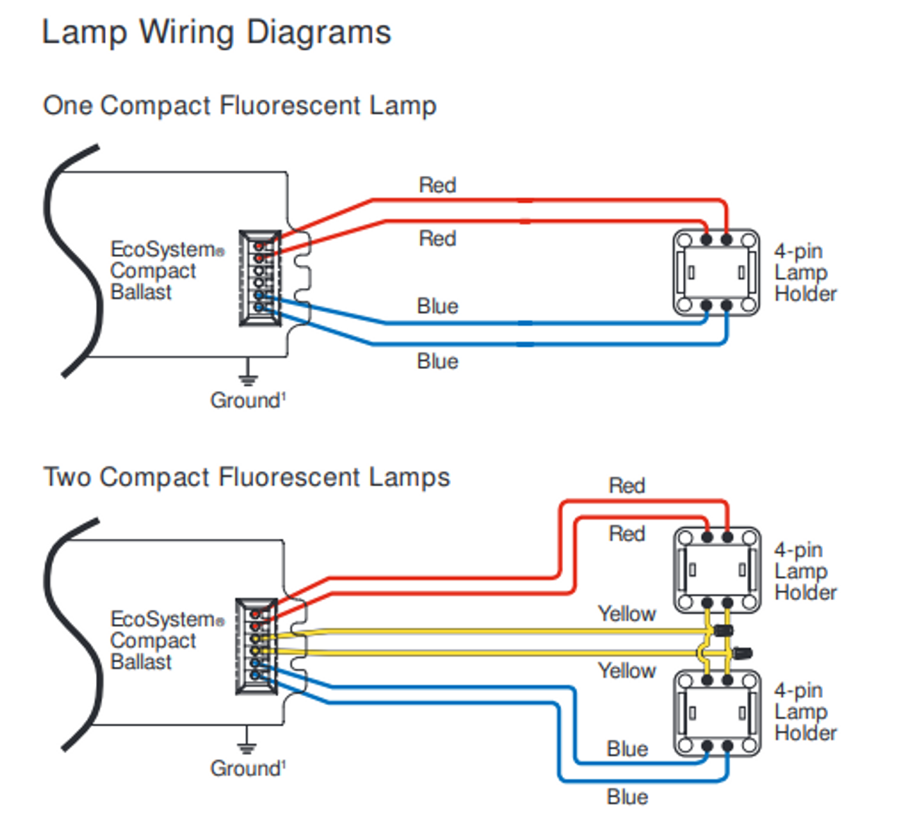
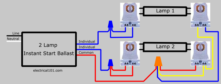
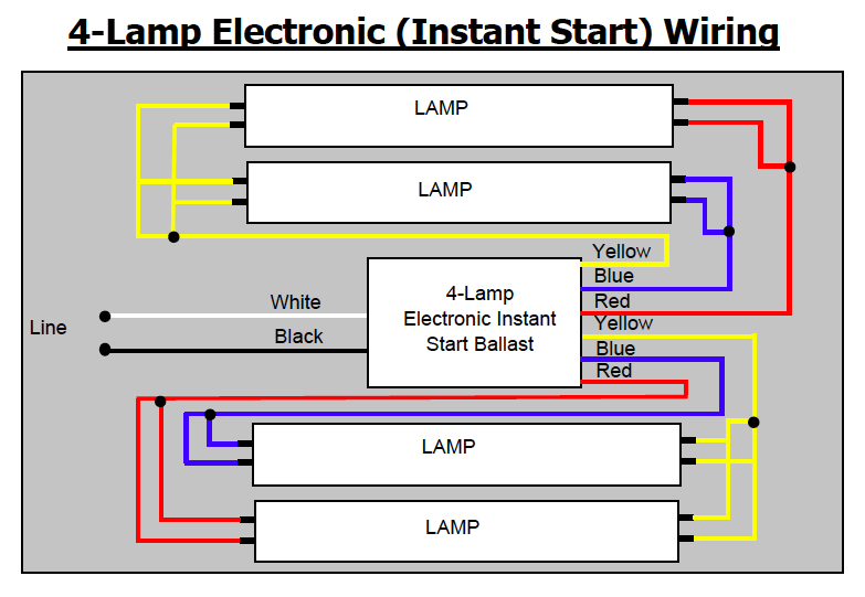
Electronic ballast diagram wiring. Philips advance ballast wiring diagram recent 2 lamp t8 ballast ballast wiring diagram. Data is based upon tests performed by philips lighting n.a in a controlled. If you use electronic ballasts, the wiring diagram looks like the following:
1 lamp rapid start ballast diagram 1 lamp instant start ballast diagram wired in series wired in parallel Wiring diagram the wiring diagram that appears above is for the lamp type denoted by the asterisk standard lead length inches in. Changing the wiring on a fluorescent light fixture from rapid start to instant start, involves changing the wiring from series to parallel.
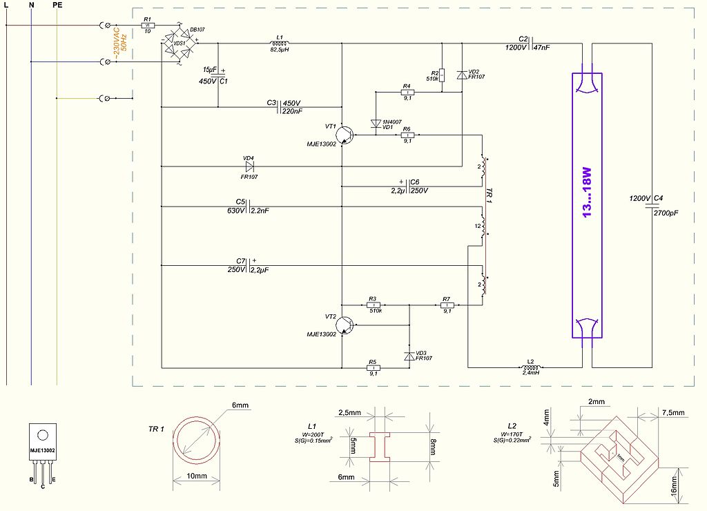
The circuit diagram of the electronic ballast is illustrated in fig.2. A wiring diagram is a simplified standard photographic depiction of an electrical circuit. Wiring diagram 1 to 2 circuit i (lamps 1,2) 4' 16' 4' 16' rss296at* 120v 1.60 190 950 1,2 circuit i (lamps 1,2) 4' 16'.
It comes with a wiring diagram affixed to the ballast and. It is extremely simple to draw a wiring diagram; 1 basic circuit diagram of an electronic ballast using resonant inverter.
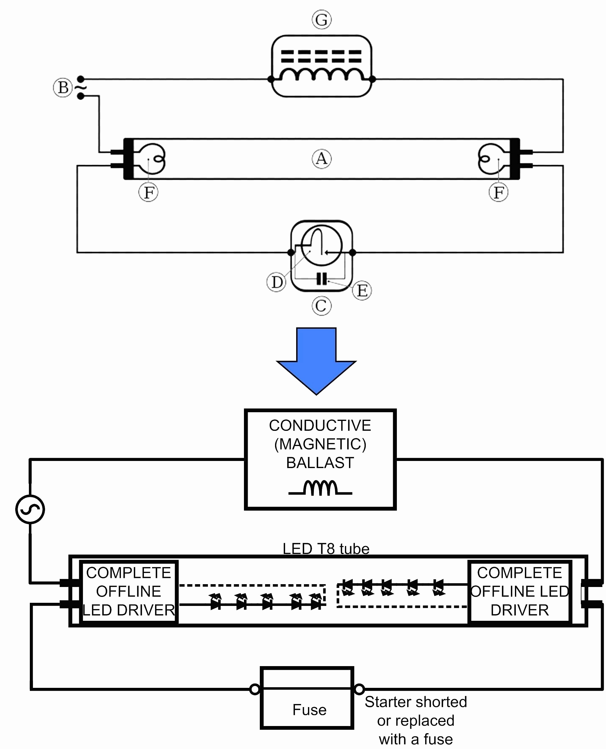
Wiring diagram how to bypass ballast for led tube. April 27, 2018 by headcontrolsystem. On the other hand, this diagram is a simplified variant of the structure.
Series ballasts can only be wired in series according to the diagram on the ballast. Assortment of electronic ballast wiring diagram. Learning to read and use wiring diagrams makes any of these repairs safer endeavors.
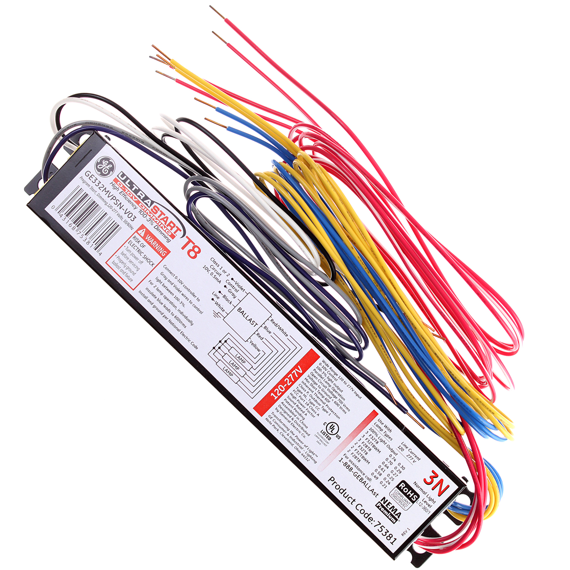
Assortment of electronic ballast wiring diagram. Ge offers electronic ballasts for a wide range of applications. Facturer is listed for ac ballasts that have unique wiring arrangements.
The first element is symbol that indicate electrical component from the circuit. Iec 6096860969 as control gear is often built into a luminaire the most. According to earlier the lines in a 2 lamp t12 ballast wiring diagram signifies wires.
Instant start ballasts can only be wired in parallel according to the diagram on the ballast. It does this through the principle of electrical gas discharge. It includes guidelines and diagrams for various types of wiring techniques as well as other things like lights, home windows, and so forth.
Parallel ballasts can only be wired in parallel according to the diagram on the ballast. Conventional lamp ballast the simplest form of ballast is an inductor. Ge electronic ballast options meet the material restriction.
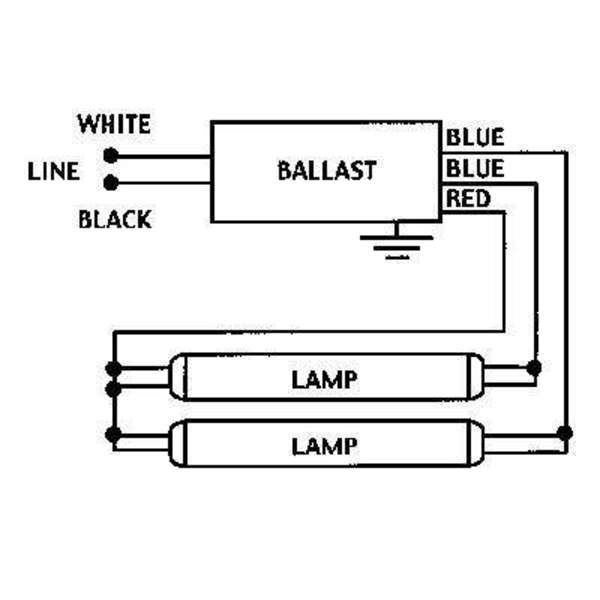
Select the philips advance electronic ballast which. The fluorescent tube has two filaments with four terminals the starter is connected between two filaments, the ballast is connected between main ac supply and one filament in tube light. A circuit is generally composed by various components.
A wiring diagram usually offers info concerning the. A current source type charge pump high power factor electronic ballast combined with buck converter. Analysis, selection, and design of resonant inverters for electronic ballasts.
The other thing that you will get a circuit diagram would be traces. Icn 4s54 90c 2ls g. A wiring diagram is an easy visual representation from the physical connections and physical layout of an electrical system or circuit.
There are just two things that will be found in almost any fluorescent ballast wiring diagram. You just require to have a good comprehension on different types of wiring and their purposes. Electronic ballast ballast, electronics, circuit diagram
Electronic ballast circuit diagram pdf. T8 lamps with a newer. An electronic ballast (or electrical ballast) is a device that controls the starting voltage and the operating currents of lighting devices.
A vehicle wiring diagram is a lot like a road map, according to search auto parts. This one was easy to wire and installed like the original/5(). Adjoining cable routes might be shown around where certain receptacles or components need to get on an usual circuit.
You will be capable to learn specifically when the projects ought to be completed, that makes it much simpler for you to effectively handle your time and efforts. Changing the wiring on a fluorescent light fixture from series to parallel, involves changing the ballast from a series to a. Electronic ballast ballast, electronics, circuit diagram from www.pinterest.dk.
Subjects that will be dealt with. Electronic ballast tube light wiring diagram connection and working we need tube light, ballast, starter and fluorescent light holders to make wiring connection. It reveals the components of the circuit as streamlined forms, and also the power and signal connections in between the devices.

T8 Electronic Ballast Wiring Diagram Gallery
File 208 Volt Hp Ballast Wiring Diagram

[DIAGRAM] Electronic Ballast Schematic Diagram FULL Version HD Quality Schematic Diagram
Ge Ultramax Ballast Wiring Diagram

T8 Electronic Ballast Wiring Diagram Gallery

Electronic Ballast Wiring Diagram Free Wiring Diagram
T12 Electronic Ballast Wiring Diagram

SunPark SL15T Electronic Replacement Ballast
T8 Electronic Ballast Wiring Diagram

Wiring Diagram For T12 Ballast
T12 8ft Ballast Wiring Diagram
Ballast Wiring Diagram T8 Wiring Diagram

Find Out Here T8 Electronic Ballast Wiring Diagram Download

[DIAGRAM] Electronic Ballast Schematic Diagram FULL Version HD Quality Schematic Diagram
Ge T12 Ballast Wiring Diagram
Ballast Wiring Diagram Cadician's Blog

Find Out Here Ge T12 Ballast Wiring Diagram Sample

Find Out Here T8 Electronic Ballast Wiring Diagram Download

[DIAGRAM] Electronic Ballast Schematic Diagram FULL Version HD Quality Schematic Diagram