5 Pin Relay Wiring Diagram Ground Trigger
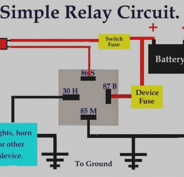
Wiring diagram terminal 86 12v trigger terminal 85 ground trigger terminal 30 12v source terminal 87 connects to device terminal 87a. There is a relay in the under hood fuse box , blower motor relay.when switched to high it energizes the relay allowing power from the hvac fuse /30 amp to flow direct to the blower motor.
Hournine Racecraft Relays
Page 5 latching relay (vw type) 30 s 56a 56b 56 latching relay are a mechanical switching device that alternates output power from terminal “56” to either “56a” or “56b”.

5 pin relay wiring diagram ground trigger. The bottom end of your relay coil has 12v on it when it is not pulled to ground. 5 pin relays provide 2 pins (85 & 86) to control the coil and 3 pins (30, 87 & 87a) which switch power between two circuits. A wiring diagram is a simplified traditional pictorial depiction of an electrical circuit.
Convert a negative output to a positive output relay wiring diagram: The high current circuit in this relay feeds. Best relay wiring diagram 5 pin bosch endearing enchanting blurts.
Terminal #85/ground is the industry standard for good quality relays, with or without a diode. Connect the pins 85 and 86 of the relay to control the coil. The police are pretty confident that he has a jiggle key (the cars have been mostly recovered, d.
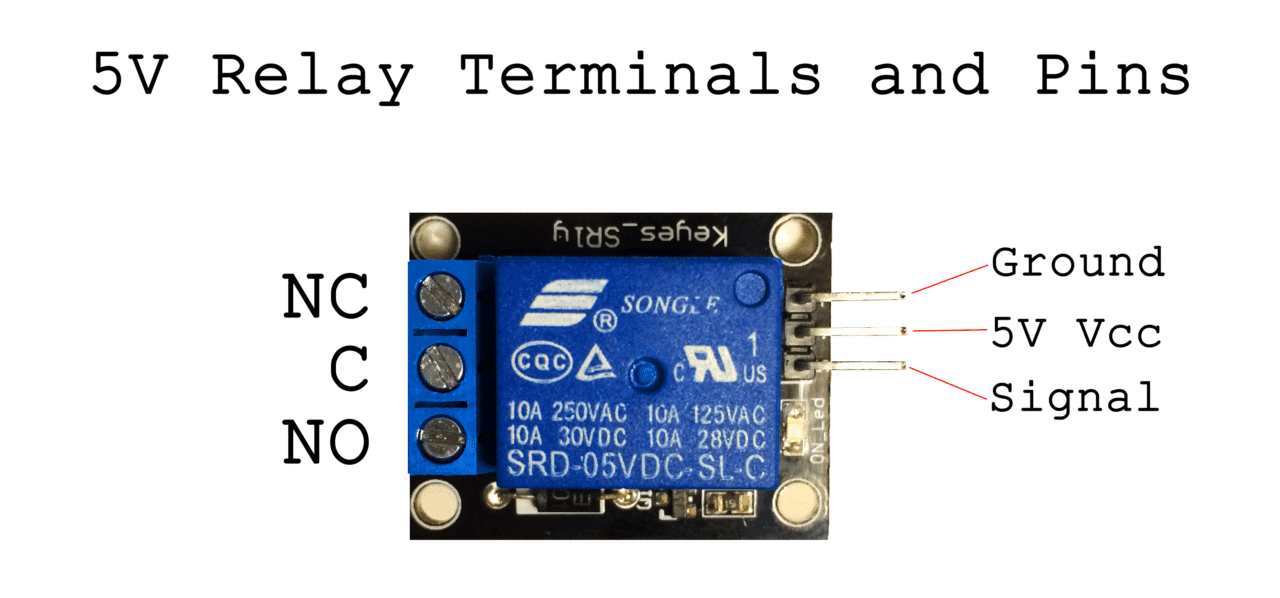
It is made up of two circuits, a coil and high amperage circuit. From pin 30 to pin 87 , if you look on the side of the relay there is a diagram.for all other speeds the current flows from the switch through the resistor. The other side has three low voltage pins (ground, vcc, and signal) which connect to the arduino.
A normally closed relay will switch power off for a circuit when the coil is activated. Current splits inside the relay, supplying power to both the control and load circuits. Each circuit has its pin numbers and wiring diagram.
If you want a normally open relay, you will wire to 87. As soon as the coil is initiated, power will be shifted from the normally closed pin to the normally open pin. If you have a switch or an alarm or keyless entry that has a negative output that you wish to use to switch a device that requires 12v+ such as a horn, dome light, parking lights, head lights, hatch release, etc., wire a relay as shown below to convert the negative output (trigger) to a positive output.
Momentarily grounding the “s” terminal switches the relay permanently to either “56a” or “56b”. 5 pin relay wiring check up. 1) your relay coil takes more current than the microcontroller can supply.
They incorporate both normally open and normally closed connect pins. In this video, i explain why it is necessary to use a relay in a circuit. It is extremely easy to attract a wiring diagram;
When pin 86 is triggered, the relay closes the circuit from 30/51 to 87. That's why i'm trying to fiddle with the wires. Below is the complete guide about automotive relay diagrams such as four and five pin relay wiring diagram in easy to understand language.
How the 5v relay works. What is 86 on a relay? An automotive relay is an electrical switch, which turns on and off by giving an electrical trigger.
For wiring the fog lights with the help of 5 pin relay, we will have to follow the below mentioned steps: Other relay variations include three and five pin relays. Although most relays are labeled on the bottom, for easy identification to the power source, you can always find the 30 pin set center and perpendicular to the output pins.
The path is altered every time the “s” terminal is grounded. If you want a closed relay, you will want to wire to 87a. I then demonstrate how to wire a 5 pin relay with a negative trigger wire.
5v relay pin diagram click the image to enlarge it relay pin configuration. 2) the output voltage of the microcontroller is either 0v or 5v. Bosch relay wiring diagram image.
With this sort of an illustrative manual, you are going to have the ability to troubleshoot, stop, and complete your projects without difficulty. You just need to have a great understanding on various types of wiring and also their objectives. Weak negative output to strong ground relay wiring diagram converting polarity with spdt relays how guides applications 1 pack 40 30 amp 12 v dc waterproof and harness heavy duty awg tinned copper wires 5 pin bosch style automotive online in indonesia b074qv54v1 autoswitch basics for the novice case use why you need.
On how you need the switch to work. 85/86 are the control side from your switch. Here, pins 30, 87, and 87a of the relay switching off the power between the two circuits.
Switched power to one, ground the other. 5 pin relay 2 pins (85 & 86) are required by the 5 pin relay to power the coil, and 3 pins are used (30, 87 & 87a) that are supposed to shift power among two circuits. A normally open relay will switch power on for a circuit when the coil is activated.
You don't need an optocoupler unless there is a need to electrically isolate the controller power supply from the relay coil.

View topic Spots boomslang

Stage 4 Complete Beginner's Guide For Arduino Hardware

77 Luxury 5 Pin Bosch Relay Wiring Diagram

Electric fuel pump relay BMW 2002 and other '02 BMW

Bosch Relay Wiring Diagram Cadician's Blog

Related image Automotive electrical, Automotive mechanic

5 Pin Relay Wiring Ground Trigger GRAMWIR
How to Set Up a 5V Relay on the Arduino Circuit Basics
Electric fans with relay wiring Ford Mustang Forum

4PinWiringSchematic RAUR.US

5 Pin Relay 12V Relay 12v 40a 5 Pin Relay 12 Volt 40

Best Relay Wiring Diagram 5 Pin Wiring Diagram Bosch 5 Pin
Basic Car Alarm Wiring Diagram schematic and wiring diagram

Bosch Relay Wiring Diagram

Wiring Diagram For 5 Pin Relay For Drl With Turn Signal Wire
5 Pin Relay Wiring Ground Trigger GRAMWIR


12 Volt Battery Charger Wiring Diagram Free Download
Solenoid Switch Wiring Diagram The Wiring (2022)

Wiring Diagram 6 Volt Positive Ground Wiring Sample